- 您现在的位置:买卖IC网 > Sheet目录3871 > PIC18F83J11T-I/PT (Microchip Technology)IC PIC MCU FLASH 4KX16 80TQFP
2010 Microchip Technology Inc.
DS39774D-page 151
PIC18F85J11 FAMILY
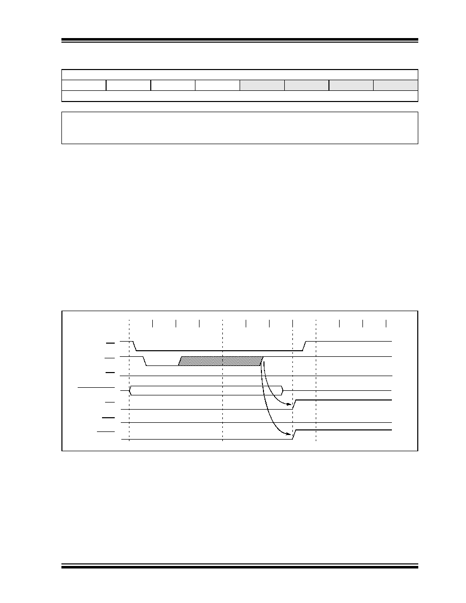
FIGURE 11-4:
PARALLEL SLAVE PORT WRITE WAVEFORMS
REGISTER 11-1:
PSPCON: PARALLEL SLAVE PORT CONTROL REGISTER
R-0
R/W-0
U-0
IBF
OBF
IBOV
PSPMODE
—
bit 7
bit 0
Legend:
R = Readable bit
W = Writable bit
U = Unimplemented bit, read as ‘0’
-n = Value at POR
‘1’ = Bit is set
‘0’ = Bit is cleared
x = Bit is unknown
bit 7
IBF: Input Buffer Full Status bit
1
= A word has been received and is waiting to be read by the CPU
0
= No word has been received
bit 6
OBF: Output Buffer Full Status bit
1
= The output buffer still holds a previously written word
0
= The output buffer has been read
bit 5
IBOV: Input Buffer Overflow Detect bit
1
= A write occurred when a previously input word has not been read (must be cleared in software)
0
= No overflow occurred
bit 4
PSPMODE: Parallel Slave Port Mode Select bit
1
= Parallel Slave Port mode
0
= General Purpose I/O mode
bit 3-0
Unimplemented: Read as ‘0’
Q1
Q2
Q3
Q4
CS
Q1
Q2
Q3
Q4
Q1
Q2
Q3
Q4
WR
RD
IBF
OBF
PSPIF
PORTD<7:0>
发布紧急采购,3分钟左右您将得到回复。
相关PDF资料
PIC16LF627-04/P
IC MCU FLASH 1KX14 COMP 18DIP
PIC18F86J55T-I/PT
IC PIC MCU FLASH 48KX16 80TQFP
PIC18F43K22-I/MV
MCU PIC 8KB FLASH 40QFN
PIC16C55A-04I/P
IC MCU OTP 512X12 28DIP
PIC18LF43K22-I/MV
MCU PIC 8KB FLASH 40UQFN
PIC16C622A-20I/P
IC MCU OTP 2KX14 COMP 18DIP
PIC18F84J11T-I/PT
IC PIC MCU FLASH 8KX16 80TQFP
PIC18F24K22-I/SP
IC PIC MCU 16KB FLASH 28SPDIP
相关代理商/技术参数
PIC18F83J90-I/PT
功能描述:8位微控制器 -MCU 8KB FL 1024b RAM 67I/O 8b Fam RoHS:否 制造商:Silicon Labs 核心:8051 处理器系列:C8051F39x 数据总线宽度:8 bit 最大时钟频率:50 MHz 程序存储器大小:16 KB 数据 RAM 大小:1 KB 片上 ADC:Yes 工作电源电压:1.8 V to 3.6 V 工作温度范围:- 40 C to + 105 C 封装 / 箱体:QFN-20 安装风格:SMD/SMT
PIC18F83J90T-I/PT
功能描述:8位微控制器 -MCU 8KB Flash 1024bytes-RAM 67I/O RoHS:否 制造商:Silicon Labs 核心:8051 处理器系列:C8051F39x 数据总线宽度:8 bit 最大时钟频率:50 MHz 程序存储器大小:16 KB 数据 RAM 大小:1 KB 片上 ADC:Yes 工作电源电压:1.8 V to 3.6 V 工作温度范围:- 40 C to + 105 C 封装 / 箱体:QFN-20 安装风格:SMD/SMT
PIC18F8410-E/PT
功能描述:8位微控制器 -MCU 16kBF 768RM 70I/O RoHS:否 制造商:Silicon Labs 核心:8051 处理器系列:C8051F39x 数据总线宽度:8 bit 最大时钟频率:50 MHz 程序存储器大小:16 KB 数据 RAM 大小:1 KB 片上 ADC:Yes 工作电源电压:1.8 V to 3.6 V 工作温度范围:- 40 C to + 105 C 封装 / 箱体:QFN-20 安装风格:SMD/SMT
PIC18F8410-I/PT
功能描述:8位微控制器 -MCU 16kBF 768RM 70I/O RoHS:否 制造商:Silicon Labs 核心:8051 处理器系列:C8051F39x 数据总线宽度:8 bit 最大时钟频率:50 MHz 程序存储器大小:16 KB 数据 RAM 大小:1 KB 片上 ADC:Yes 工作电源电压:1.8 V to 3.6 V 工作温度范围:- 40 C to + 105 C 封装 / 箱体:QFN-20 安装风格:SMD/SMT
PIC18F8410T-I/PT
功能描述:8位微控制器 -MCU 16kBF 768RM 70I/O RoHS:否 制造商:Silicon Labs 核心:8051 处理器系列:C8051F39x 数据总线宽度:8 bit 最大时钟频率:50 MHz 程序存储器大小:16 KB 数据 RAM 大小:1 KB 片上 ADC:Yes 工作电源电压:1.8 V to 3.6 V 工作温度范围:- 40 C to + 105 C 封装 / 箱体:QFN-20 安装风格:SMD/SMT
PIC18F8490-E/PT
功能描述:8位微控制器 -MCU 16kBF 768RM 66I/O RoHS:否 制造商:Silicon Labs 核心:8051 处理器系列:C8051F39x 数据总线宽度:8 bit 最大时钟频率:50 MHz 程序存储器大小:16 KB 数据 RAM 大小:1 KB 片上 ADC:Yes 工作电源电压:1.8 V to 3.6 V 工作温度范围:- 40 C to + 105 C 封装 / 箱体:QFN-20 安装风格:SMD/SMT
PIC18F8490-I/PT
功能描述:8位微控制器 -MCU 16kBF 768RM 66I/O RoHS:否 制造商:Silicon Labs 核心:8051 处理器系列:C8051F39x 数据总线宽度:8 bit 最大时钟频率:50 MHz 程序存储器大小:16 KB 数据 RAM 大小:1 KB 片上 ADC:Yes 工作电源电压:1.8 V to 3.6 V 工作温度范围:- 40 C to + 105 C 封装 / 箱体:QFN-20 安装风格:SMD/SMT
PIC18F8490-I/PT
制造商:Microchip Technology Inc 功能描述:IC 8BIT FLASH MCU 18F8490 TQFP80